When thinking about robots, it is easy to view them as a symbol of the future. But what if I told you robots are already a huge part of our everyday lives?
Robots have become a central factor in manufacturing, completing repetitive tasks and reducing margins of error in these tasks. Similar to a new employee who has to complete on-the-job training, a robot has to be taught the operation. In this article, we will highlight some basics of robot teaching.
Programming the Robots
There are several ways to program robots. Some include programming them in robotic coordinates, programming them in workspace coordinates, or performing a direct teach-and-learn. When choosing which method to use, it is important to consider the application of your robot. Your application will dictate whether there is a need to handle variation in tool path or even “re-tooling”, which is the switching of the application of the robot to an entirely different process like roughing to gluing or cutting to welding, and so on.
I think it would be helpful to state that robots understand their placement and movement in their work environment through the use of coordinate systems. A coordinate is a position on a 3D map around the robot. There are two common types of coordinates systems: Cartesian and Polar. A Cartesian coordinate system is much like a piece of grid paper that has X row and Y column positions, combined with a height Z off of the paper. A Polar coordinate system is like a globe map with latitude, longitude, and distance from the center. In each system, a unique position for the location of the robot and the position of its end effector can be described very accurately.
Introducting Robot Positioning

Robot position and end effector location are easily identified absolutes. However, the path for moving an end effector from one location to another is filled with obstacles and the potential of damaging collisions. Also, the type of robot affects the complexity of maneuvering safely. A simple gantry robot can reach an infinite number of exact positions within its workspace. For every unique point, there is exactly one combination of rail positions that will reach that location. Gantry robots excel for some operations, like electronics pick and place, but they cannot work around significant obstructions.
Robots that use articulating arms, on the other hand, can reach an infinite number of unique locations within their work area and have a great capacity for arching around obstacles. With this flexibility comes the burden that an infinite number of arm orientations can reach every unique location. This can make programming much more complicated.
Robot Teaching and the MicroScribe Digitizer
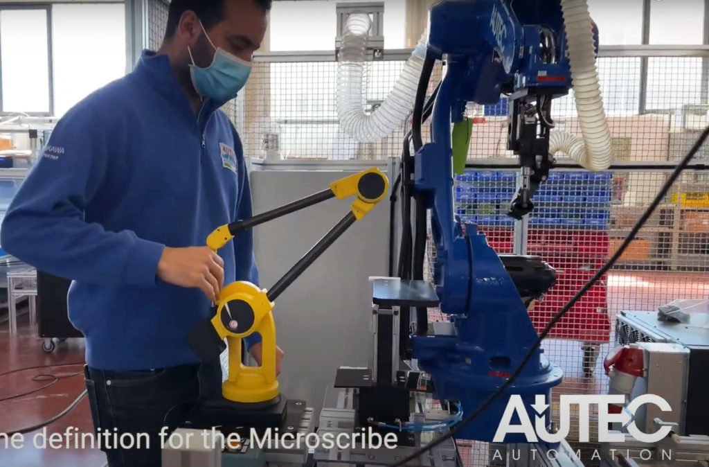
One of the values of the MicroScribe portable digitizer is that it models a stable, efficient kinematic arm sequence from its base origin to the probe tip. It supplies an accurate end effector position along with a roll, pitch, yaw orientation vector. Matching joint angles and arm segment parameters can be gathered in association with each other to completely model a valid path to the desired location. If the kinematics of the robot’s chain are similar to the MicroScribe chain, we can take the output telemetry from the MicroScribe arm and directly tell the robot to mimic the movement. If the kinematics are too dissimilar, the path may not reliably account for avoidance. in such cases, having good position and roll, pitch, and yaw descriptions of the end effector are usually sufficient to allow the robot’s control software to derive its own kinematic path.
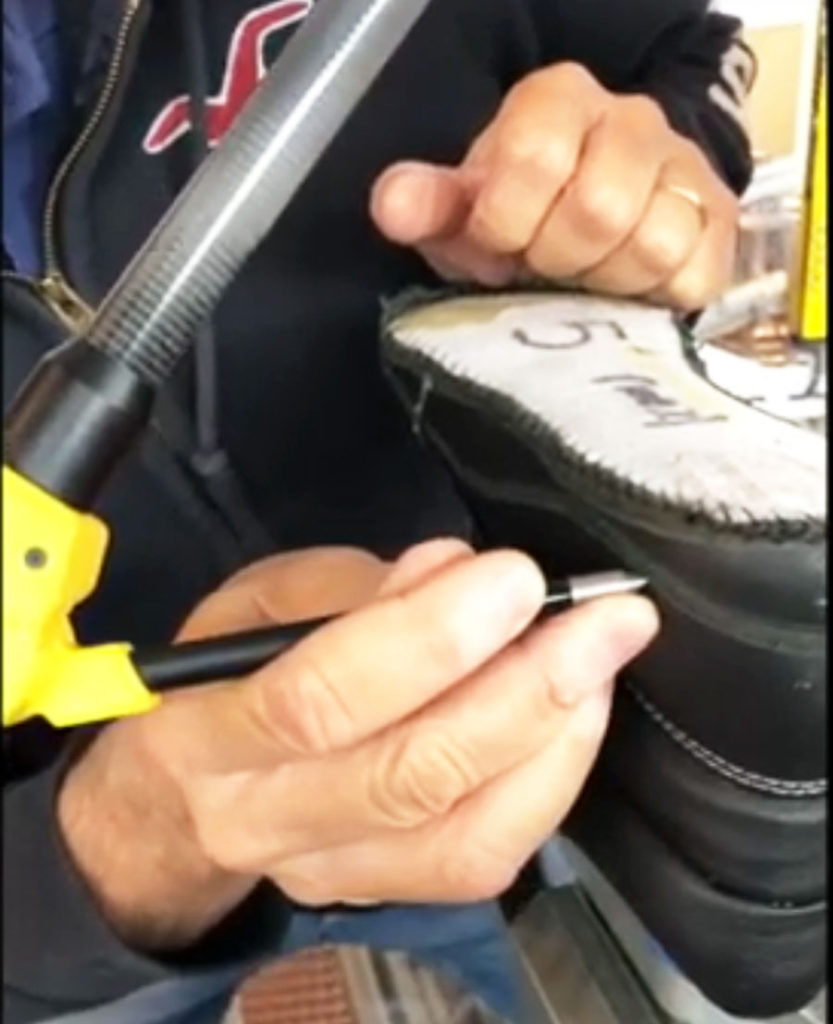
When MicroScribe kinematics and robot kinematics are similar, programming tasks can be as simple as having the robot mirror the MicroScribe movements. This saves many programming steps, and validations improve accuracy. Several of our customers use a MicroScribe digitizer to teach robots in the fields of biomechanical research, industrial automation, and robotic medical procedure planning. For example, one of our European customers builds automation systems for shoe manufacturers. They employ a MicroScribe digitizer to measure samples shoes to set efficient cutting, roughing, and gluing paths for production robots. They have reduced an hour plus trial-and-error procedure and reduced it to a predictable 5-minute process per shoe sample.
MicroScribe Digitizer as an Invaluable Tool

This example of direct path creation only involves the MicroScribe digitizer end effector and RPY vector. The probe tip identifies the end effector (X, Y, Z) along the intended toolpath as well as the tool orientation (R, P, Y) for each point in the path set. Direct path creation is an excellent MicroScribe application. Other effective uses of the MicroScribe digitizer are to orient robots to alternative coordinate systems and to validate robot positioning.
Most importantly, the MicroScribe portable digitizer is a crucial tool in achieving the kinematic work of setting up robot positioning. Robot teaching is pivotal in processes that create our everyday realities. Ultimately, the MicroScribe has a direct impact on manufacturing processes by enhancing production and remaining competitive in the field. Next time you think about robots in space, remember that they might have helped create your shoes!
If you liked this article, check out our other posts and press releases here. To learn more about using the MicroScribe arm for robot teaching, check out these YouTube video demonstrations by AUTEC Automation demonstrating tool path creation and robot programming!
Copyright© 2021 Revware Inc. All rights reserved. Reuse and reprint allowed only with permission by Revware Inc., and with appropriate acknowledgments.
About Revware
Revware provides high, quality, simple to use, innovative, cost-effective modeling solutions to solve your design, metrology, and engineering problems.
