When following any process, there are certain strategies you can use to improve your efficiency, like studying road signs before you drive, or spending a few minutes stretching before you exercise. These preparations may not be critical for success, but they certainly make your process easier and ensure a better result, whatever your activity may be. This certainly applies to the collection of 3D data from a real-world part or object and rendering it in your CAD environment.
What is alignment?
There are three key work elements to set up in your workspace in order to digitize a part: a CAD program (presumably on a PC), your digitizer (scanner or portable CMM), and the part you wish to measure or replicate. After you connect your digitizer to your CAD application and calibrate or ‘home’ the device, your digitizer and CAD software will share a common coordinate system. The part you wish to digitize, however, still has its own location on a table or fixture and is still ‘out in space’ from the CAD system’s perspective.
By setting a part coordinate system and defining it, you create a matrix that describes the rotations and translations you get from the device’s coordinate system into the part coordinate system, giving them a common frame of reference, so that scanned data from the real-world object easily translates into the design world of the CAD environment. Essentially, you are shifting the origin and orientation of where the digitizer believes is home.

While the device’s coordinate system is never altered, the alignment matrix functions as an interpreter between the data and CAD environment to ultimately create a new coordinate system for the part.
Why is alignment important?
There are three main reasons why setting up a part alignment in your workspace is advantageous. First, setting a reference frame common to both your part and the CAD/digitizer system is efficient and makes modeling the part easier for you, the observer.
When you set up your coordinate system (Cartesian, in this example) with an origin (0,0,0) in close physical proximity to the part with the axes (x,y,z) aligned and then bring it up in a CAD system, it comes up near the origin for easy viewing.
If you have not aligned the coordinate system of your part to a coordinate system in your CAD program, the data may not appear where you expect to find it. Then, when you open the CAD file after digitizing the part model, it looks like there is no data. The data points of the part are there but are located somewhere ‘out in space’ in the CAD file’s coordinate system, resulting in the added step of recentering the image.
Second, it’s essential to maintain reproducibility of the measurement environment. There are a range of ways data loss can occur, from your CAD computer system failing to someone bumping the table or your measuring device. These can be data disasters unless you can recreate the coordinate system. By taking the time to align, you are investing in your time, effort, and data integrity.
Finally, the act of aligning your physical coordinate system to your CAD internal coordinate system is convenient. With some projects, multiple days of work may be required. This involves walking away from your project, which you can confidently do if your part coordinate system is set. The element of accessibility that aligning provides is also beneficial in situations where more data needs to be extracted from the item sometime later.
Instead of having to re-digitize the part to get perfect registration between the previous work and new, you just realign the part and the new information collected will sync right up with your previous work.

How do I create an alignment?
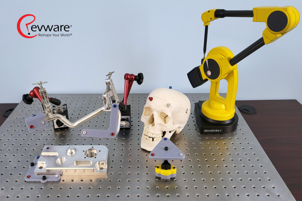
Overall, having a reproduceable alignment is the goal. This can be achieved in several ways. You can create a reference frame by using the natural structure of your part to create reproducible data locations. For example, a forensic scientist measuring a specimen skull notices suture intersections where the probe can fit reproducibly into intersections on the surface. If they need to reestablish the alignment now or in the future the probe tip will fall back into that same confluence every time.
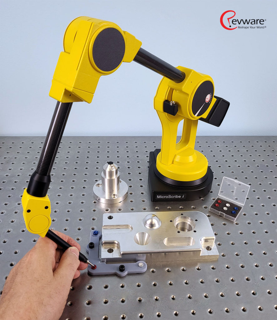
Alternately, you can attach something like a marker or fixture to the part, either as individual points or a cluster of points in a jig, which become your reference. It is important to note when using jigs they must be stable and not move relative to the part in order to be reproduceable.
There are also jigs you can set up in a workspace so that a part fits into the jig in a known, repeatable way. Every time you measure the jig, its reference points should have the same relationship to each other and to the part. Thus, it is possible to use the jig to define your coordinate system with an easily identifiable offset.
How can we help you with this process?
Visit our web store for alignment divots that can be easily fixed to (and removed from) your part or object to make alignment easy. While these “dots” are intended to be disposable, your data is not. Our team is fully supportive of data integrity, and alignment is a great method to ensure your measurements are safe and correct.
More information will be coming on this product soon. In the meantime, to learn why data integrity is important, visit this blog post.
Follow us on Facebook and LinkedIn!
Copyright© 2022 Revware Inc. All rights reserved. Reuse and reprint allowed only with permission by Revware Inc., and with appropriate acknowledgments.
About Revware
Revware provides high, quality, simple to use, innovative, cost-effective modeling solutions to solve your design, metrology, and engineering problems.
